Two-Wire, Zero Speed
Differential Gear Tooth Sensor IC
ATS685LSH
10
Allegro MicroSystems, LLC
115 Northeast Cutoff
Worcester, Massachusetts 01615-0036 U.S.A.
1.508.853.5000; www.allegromicro.com
Power-On
The ATS685 is guaranteed to power-on in the high current state,
I
CC(High)
. When power (V
CC
> V
CC
(min) ) is applied to the
device, a short period of time is required to power the vari-
ous portions of the circuit. During this period, the ATS685 will
power-on in the high current state, I
CC(High)
.
Initial Edge Detection
The device self-calibrates using the initial teeth sensed, and then
enters running mode. This results in reduced accuracy for a brief
period, CAL
I
. However, this period allows the device to optimize
for running mode operation. As shown in figure 6, the first three
high peak signals corresponding to rising output edges are used to
calibrate AGC (Automatic Gain Control). There is a slight vari-
ance in the duration of initialization, depending on what target
feature is opposite the sensor IC when power-on occurs. Also, a
high speed of target rotation at power-on may increase the quan-
tity required in the CAL
I
period.
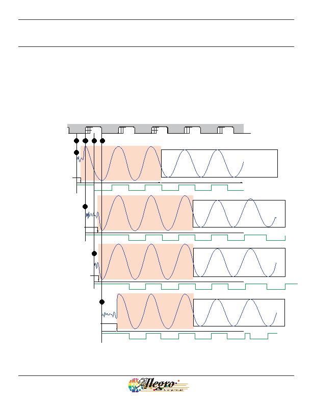
Figure 6. Power-On Initial Edge Detection. This figure demonstrates four typical power-on scenarios. All of these examples assume that the target is
moving relative to the sensor IC in the direction indicated (from pin 1 to pin 4) and the voltage output is configured for low-side sensing, V
OUT(Low)
. The
length of time required to overcome Start Mode Hysteresis, as well as the combined effect of whether it is overcome in a positive or negative direction
plus whether the next edge is in that same or opposite polarity, affect the point in time when AGC calibration begins. Three high peaks are always
required for AGC calibration when f
OP
d 200 Hz, and more may be required at greater speeds.
Target
(Gear)
I
CC
I
CC
I
CC
I
CC
I
CC
I
CC
I
CC
I
CC
Power-on
opposite
tooth
Power-on
at falling
mechanical
edge
Power-on
at rising
mechanical
edge
Power-on
opposite
valley
AGC Calibration
Running Mode
AGC Calibration
Running Mode
AGC Calibration
Running Mode
AGC Calibration
Running Mode
Device
Position
1
1
4
4
2
2
3
3
Start Mode
Hysteresis
Overcome
Start Mode
Hysteresis
Overcome
Start Mode
Hysteresis
Overcome
Start Mode
Hysteresis
Overcome
发布紧急采购,3分钟左右您将得到回复。
相关PDF资料
BU52001GUL-E2
IC HALL EFFECT SW BIPO VCSP50L1
BU52003GUL-E2
IC HALL EFFECT SW BIPO VCSP50L1
BU52014HFV-TR
IC HALL EFFECT SW BIPO HVSOF5
BU52040HFV-TR
IC HALL EFFECT BIPO LATCH HVSOF5
D6B-2P
SENSR TILT 35-65DEG 1MA SMD GUL
D7E-3
SENSOR TILT 50-80DEG 0.1A GRY
DSBA1H
SENSOR TILT SW 30-60DEG 20MA TH
EE-SA103
SENSOR OPTO SLOT 3MM TRANS THRU
相关代理商/技术参数
ATS692LSHTN-RSNPH-T
功能描述:IC HALL EFFECT SENSOR 4SIP 制造商:allegro microsystems, llc 系列:- 包装:带卷(TR) 零件状态:有效 功能:专用型 技术:霍尔效应 极化:- 感应范围:69% 跳闸,31% 释放 测试条件:-40°C ~ 150°C 电压 - 电源:4 V ~ 24 V 电流 - 电源(最大值):16.5mA 电流 - 输出(最大值):- 输出类型:电流 特性:- 工作温度:-40°C ~ 150°C(TA) 封装/外壳:4-SIP 模块 供应商器件封装:4-SIP 标准包装:800
ATS693LSGTN-RSNYPH-T
功能描述:IC HALL EFFECT SENSOR 4SIP 制造商:allegro microsystems, llc 系列:- 包装:带卷(TR) 零件状态:有效 功能:专用型 技术:霍尔效应 极化:- 感应范围:69% 跳闸,31% 释放 测试条件:-40°C ~ 150°C 电压 - 电源:4 V ~ 24 V 电流 - 电源(最大值):16.5mA 电流 - 输出(最大值):- 输出类型:电流 特性:- 工作温度:-40°C ~ 150°C(TA) 封装/外壳:4-SIP 模块 供应商器件封装:4-SIP 标准包装:800
ATS699LSN-FSWPH-T
功能描述:2-WIRE DIFFERENTIAL SPEED & DIRE 制造商:allegro microsystems, llc 系列:- 零件状态:在售 用于测量:旋转位置 技术:电阻 旋转角 - 电气,机械:- 线性范围:- 输出:电阻 输出信号:顺时针增加 致动器类型:外磁铁,不含 线性度:- 电阻容差:- 电压 - 电源:4 V ~ 24 V 安装类型:通孔 端子类型:焊接垫 工作温度:-40°C ~ 150°C 标准包装:2,400
ATS699LSN-RSWPH-T
功能描述:2-WIRE DIFFERENTIAL SPEED & DIRE 制造商:allegro microsystems, llc 系列:- 零件状态:在售 用于测量:旋转位置 技术:电阻 旋转角 - 电气,机械:- 线性范围:- 输出:电阻 输出信号:顺时针增加 致动器类型:外磁铁,不含 线性度:- 电阻容差:- 电压 - 电源:4 V ~ 24 V 安装类型:通孔 端子类型:焊接垫 工作温度:-40°C ~ 150°C 标准包装:2,400
ATS75
制造商:未知厂家 制造商全称:未知厂家 功能描述:LOW- OLTAGE 2-WIRE DIGITAL TEMPERATURE SENSOR With Thermal Alarm
ATS75D8
制造商:未知厂家 制造商全称:未知厂家 功能描述:LOW- OLTAGE 2-WIRE DIGITAL TEMPERATURE SENSOR With Thermal Alarm
ATS75M8
制造商:未知厂家 制造商全称:未知厂家 功能描述:LOW- OLTAGE 2-WIRE DIGITAL TEMPERATURE SENSOR With Thermal Alarm
